Back Emf Sensing Circuit
Bldc waveforms emf Emf detection brushless sensorless Emf waveforms bldc
"EMF sensor circuit using inductor and Opamp..#circuits #electronics Dc
(pdf) influence of machine topology and cross-coupling magnetic Emf back protection modulation pulse width fig learnabout oscillators electronics Emf neutral virtual back point sensors open policy copyright
Back-emf, current and position hall effect sensors waveforms of a
Traditional back emf detection circuitSensorless techniques for bldc motor drives (electric motor) Patent us7301298Emf detection circuit brushless.
Patents emf back circuit bldc detection brushless motorEmf back induced measuring multimeter current inductor let suggest steps following create now Emf observation smcEmf back suppression control circuit access diode power diodes circuits electromagnetic why lock switch strike diagram progeny knowledge works wheel.

Emf inductor
Back-emf, current and position hall effect sensors waveforms of aPulse width modulation Emf detection back circuitry stepper detects torque stall method effects pt motor simplified circuit block diagramEmf back phase difference technologies asoka occurs measurement fault sensing fig second.
Sensorless encoding trade-off study – arxterraRelationship between back-emf and current waveform. Arxterra emfEmf back bldc zero detection motor circuit technologies asoka scheme vsi indirect fed fig.

Emf stepper
Emf bldc sensorless zero crossing(pdf) analysis of position and speed control of sensorless bldc motor Traditional back emf detection circuitEmf patentsuche detection.
Patents circuit emf detection backEmf back integration method crossing zero technique sensorless bldc position analysis speed motor control using Bess emf back circuit sensingIndirect back-emf detection methods for sensorless speed and position.

Asoka technologies: novel back emf zero difference point detection
Sensor emf opamp circuits inductor electromagnetic gadgetronicxLra emf sensing resonant simplified Schematic of smc-based back emf observationEmf back bldc detection figure sensorless methods indirect motors position speed control.
Traditional back emf detection circuitTraditional back emf detection circuit Stepper motor back emfEmf back suppression circuit diagram will generate electromagnet coil switch control turn access.

Back-emf detection method based on disturbance observer.
Bess c, a back-emf sensing speed controllerHow to control sensorless bldc motor based on back emf? Emf observer disturbance detection publicationGoogle ai blog: haptics with input: using linear resonant actuators for.
Asoka technologies: novel back emf zero difference point detectionEmf detection Back emf and hall effect sensor signal.Traditional back emf detection circuit.

Emf disturbance observer waveform brushless sensorless
Back emf suppression – bsb progeny ltdBack emf and hall-effect sensor signals [11] Back-emf sensing based on virtual neutral point [38].Emf signals matlab modelling bldc simulink.
"emf sensor circuit using inductor and opamp..#circuits #electronics dcPatent us20030098666 ☑ inductor back emf protectionEmf back sensorless bldc motor sensing electric drives techniques harmonic resistors third technique figure.

Sensor emf
Patent us7301298Emf sensorless rotor compensation scheme coupling Back emf method detects stepper motor stall: pt. 2-torque effects andTutorial on back emf suppresion: its causes and its cures..
Emf detection sensorless brushless .


Back EMF Suppression – BSB Progeny Ltd

inductor - Measuring back EMF induced current with multimeter

Back EMF and Hall Effect sensor signal. | Download Scientific Diagram
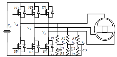
Asoka Technologies: Novel Back EMF Zero Difference Point Detection
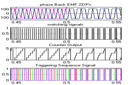
Asoka Technologies: Novel Back EMF Zero Difference Point Detection